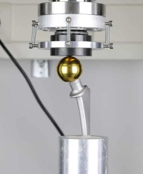
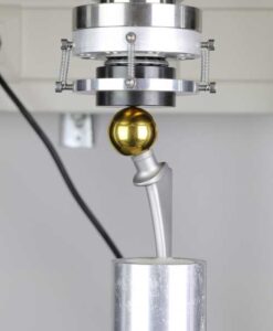
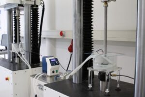
ISO 7206-4 and ISO 7206-6 – Fatigue testing*

ISO 7206-4 und -6 DauerschwingprüfungThe tests according to ISO 7206-4 and ISO 7206-6 focus on the stem and neck regions of the femoral component of hip replacements. Under specified cyclic loads and numbers of cycles, the fatigue strength of the hip stem is evaluated. The fixation method and applied loads vary depending on the design and length of the stem, which is classified as short stem, standard stem, or revision stem.
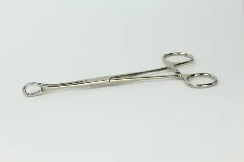
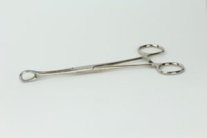
Additional requirements arise depending on whether the design is anatomical or straight. If the product features taper connections in the stem or neck area, the tests are performed in a saline bath at 37°C.

Beyond the prescribed standard conditions, we offer, in consultation with our customers, testing with higher loads, increased cycle numbers, and load increments.

23. March 2026|

ISO 11953 torque wrenches*

DIN EN ISO 11953 describes a test concerning torque wrenches used for the placement of dental implants. The objective is to verify the repeatability of the torque indication or the triggering accuracy of the torque wrench. The operating principle of torque wrenches may be based on different mechanisms, such as a bending beam with scale indication or a ratchet mechanism that signals the target torque by a clicking sound.

In clinical practice, the key question is how precisely torque values are maintained after repeated use. Using our torque testing system, combined with intermediate endurance testing and reprocessing procedures, we simulate long-term use under accelerated conditions.

23. March 2026|

ISO 3630-1 root canal instruments*

We test the mechanical requirements for root canal instruments in accordance with DIN EN ISO 3630-1:2008 and are accredited to perform testing of torsional strength and angular deflection (Section 7.4) as well as bending resistance (Section 7.5).

23. March 2026|

ASTM F2077 fusion implants*

ASTM F2077 Fusionsimplantate* We offer various test methods for the mechanical characterization of spinal fusion implants in accordance with ASTM F2077. Together with you, we select the appropriate test procedures for your individual fusion implants from the following options:

Static test methods

  1. Compression test:
    The fusion implant is placed between two steel blocks and clamped in the test fixture. The surfaces of the blocks are adapted to the implant geometry. The construct is loaded with a constant displacement (max. 25 mm/min), and the force–displacement curve is recorded and evaluated with respect to mechanical properties (including stiffness and strength) under compression.
  2. Shear test:
    This test is performed in the same manner as the compression test, except that the lower block has a base inclined by 27° or 45°. As a result, both compressive and shear loads act on the implant.
  3. Axial torsion:
    As in the compression and shear tests, the fusion implant is clamped between two blocks. Depending on the intended implantation region of the spine, an axial preload of 100 N (cervical), 300 N (thoracic), or 500 N (lumbar) is applied. While maintaining constant axial load, a rotation is applied at a constant rate (60°/min), and a torque–rotation angle curve is recorded. This curve is evaluated with respect to mechanical properties (including stiffness and strength) under torsion.

Dynamic test methods

Following the static investigations, tests are performed dynamically using new specimens over 5 million cycles, with test blocks made of polyacetal. A constant ratio between maximum and minimum load of R = 10 must be maintained for dynamic compression and shear tests, and R = 1 for dynamic torsion tests. The maximum load should correspond to 25%, 50%, or 75% of the respective maximum load. Ultimately, the difference between two load levels at which the implant either fails dynamically or survives should be less than 10%. The test ends when 5 million load cycles are reached or when mechanical failure of the implants occurs. Tests are conducted under laboratory conditions (air and room temperature), but can also be repeated in Ringer’s solution at 37 °C if required to simulate physiological environmental conditions and possible corrosive effects.

23. March 2026|

ASTM F1717 corpectomy model*

ASTM F1717 Korpektomie Modell* 
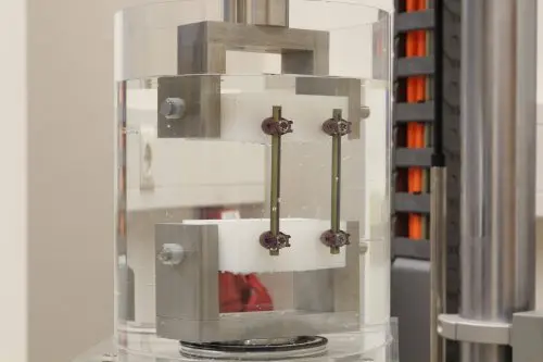
We offer various test methods for the mechanical characterization of spinal implants in a vertebrectomy model in accordance with ASTM F1717. The vertebrectomy model simulates the bridging of a vertebral body without anterior support. The spinal implants are rigidly connected to two UHMWPE blocks with well-defined material properties, while a defined gap between the blocks simulates the absence of a vertebral body. The shape and properties of the test blocks are adapted to different regions of the spine (e.g., lumbar or cervical). Together with you, we select the appropriate test procedures for your individual spinal implants from the following options:

Static test methods

  1. Bending test under compression:
    The construct consisting of test blocks and spinal implant is clamped in the test fixture and a compressive load (max. 25 mm/min) is applied. The force–displacement curve is recorded and evaluated with respect to mechanical properties (including stiffness and strength) under compression.
  2. Bending test under tension:
    The construct consisting of test blocks and spinal implant is clamped in the test fixture and a tensile load (max. 25 mm/min) is applied. The force–displacement curve is recorded and evaluated with respect to mechanical properties (including stiffness and strength) under tension.
  3. Axial torsion:
    The construct consisting of test blocks and spinal implant is clamped in the test fixture and subjected to constant torsion (max. 60°/min). The axial load should be approximately zero. The torque–rotation angle curve is recorded and evaluated with respect to mechanical properties (including stiffness and strength) under torsion.

Dynamic test methods

Following the static investigations, tests are performed dynamically using new specimens over 5 million cycles. A constant ratio between maximum and minimum load of R = 10 must be maintained. The maximum load is initially selected freely. If the implants survive 5 million cycles, the load is adjusted and testing repeated. Ultimately, the difference between two load levels at which the implant fails dynamically or survives should be less than 10%. Tests are conducted under laboratory conditions (air and room temperature), but can also be repeated in Ringer’s solution at 37 °C if required, in order to simulate physiological environmental conditions and possible corrosive effects.

INNOPROOF GmbH is accredited for dynamic testing.

23. March 2026|

Tooth preservation ISO 3630* and ISO 6876*

In addition to testing dental implants, we offer testing methods in the field of tooth preservation. These relate to endodontic instruments and root canal sealing materials.

We test the mechanical requirements for root canal instruments according to DIN EN ISO 3630-1 and are accredited for torsional strength and twist angle tests (Section 7.4) as well as bending resistance (Section 7.5). The second part of this standard, DIN EN ISO 3630-2, covers reamers, which are tested for fatigue strength in a rotary bending test.

For tooth preservation, we also test root canal sealing materials according to DIN EN ISO 6876. We are accredited for the following procedures: flow, working time, setting time, film thickness, foreign matter, and solubility.

23. March 2026|

ISO 11953 – Torque wrench*

DIN EN ISO 11953 describes a test concerning torque wrenches used for placing dental implants. The goal is to check the repeatability of the torque display or the triggering of the torque wrench. The working principle of the torque wrench can be based on various mechanisms, such as a bending beam with a scale display or a ratchet that signals reaching the desired torque by clicking.

In clinical practice, the key question for practitioners is how precise the torque values remain after a certain number of uses. With our torque testing setup combined with endurance tests and reprocessing equipment, we simulate these applications in an accelerated timeframe.

23. March 2026|

IP-06-02 – Fatigue testing of bridge constructions

For the fatigue testing of bridge constructions, INNOPROOF GmbH has established an in-house procedure, as this is currently not covered by international standards. The in-house procedure was developed by the manufacturer Nobel Biocare, Switzerland. The bridge is fixed onto two dental implants, which are embedded in a metal block.

We offer this testing procedure similar to ISO 14801 tests, conducted in medium at 37°C.

23. March 2026|

ISO 22683 – Rotation fit testing between implant and abutment*

The standard ISO 22683 defines test methods to determine the rotational fit (rotational freedom angle) between the implant body and the implant abutment. This ensures that manufacturing tolerances and clinical requirements are met and helps prevent premature loosening of the connection, especially when components from different manufacturers are combined.

23. March 2026|
Go to Top