ASTM F543 cortical bone screws*
 We offer various test methods for the mechanical characterization and classification of bone screws in accordance with ASTM F543. Together with you, we select the appropriate test procedures from the following range to suit your specific screw design:
- Test method for determining torsional properties
The bone screw is clamped in a fixture and loaded at a constant rotational speed (1–5 rpm) while a torque–rotation angle curve is recorded. This curve is then evaluated with respect to yield point, maximum torsional moment, and fracture angle, enabling a qualitative comparison of different screws. - Test method for determining insertion and removal torque
The screw is inserted into a standardized test block under a constant axial load and at a constant rotational speed (1–5 rpm), and subsequently removed, in order to determine material-independent comparative values for insertion and removal torque. - Test method for determining axial pull-out strength
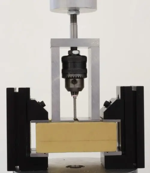
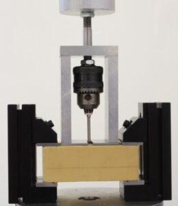
The screw is inserted into a standardized test block at a constant rotational speed (3 rpm) up to a defined insertion depth and subsequently pulled out axially at a constant speed (5 mm/min) until the screw loosens or fails. - Test method for determining the cutting performance of self-tapping bone screws
To determine the axial force at which the self-tapping action of the screw begins, the screw is inserted into a pre-drilled test block at increasing axial force (1–3 N/s) and a rotational speed of 30 rpm. - Classification of metallic bone screws
Based on various geometric characteristics, screws are classified into categories HA, HB, HC, and HD. - Classification of the connection between screw head and bit
Based on various geometric characteristics, the connections between screw head and bit (drive connection) are specified.
In addition to the mechanical characterization and classification of bone screws, we are also pleased to advise you on correct labeling, packaging, and the content of the manufacturer information to be provided with the product.
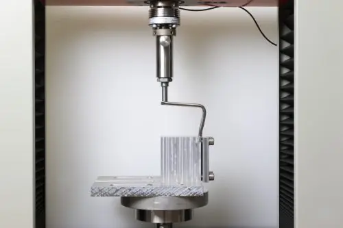
 We offer characterization of angled plates in accordance with ASTM F384. Specifically, we can perform static and dynamic bending tests:
 We offer a testing procedure in accordance with ASTM F382 for comparing bone plates with respect to their mechanical properties. Specifically, the following two tests can be performed
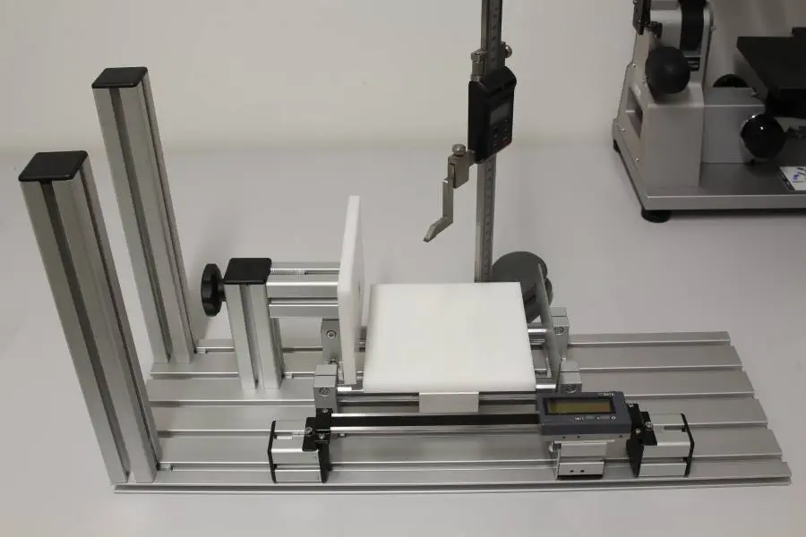
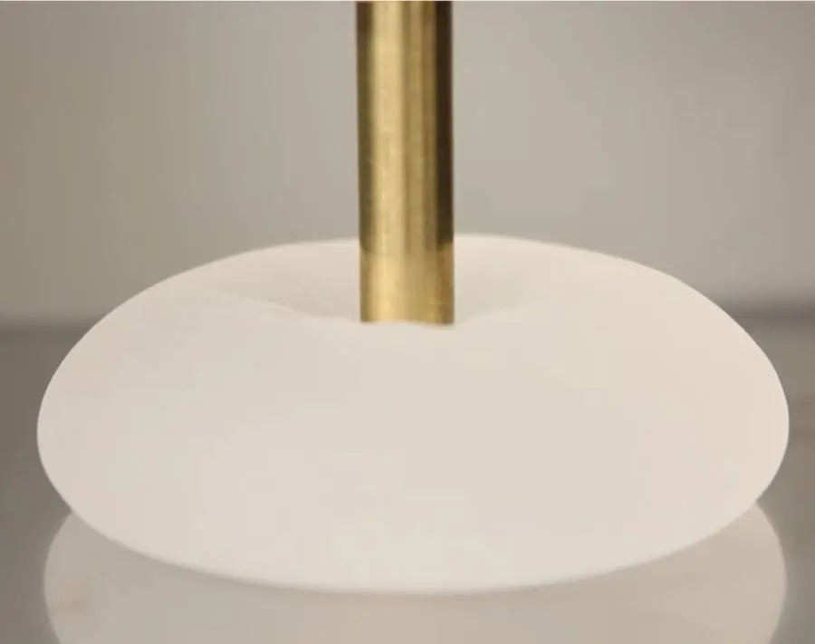
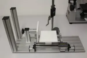 For the morphological analysis, a test setup based on Jewell et al. 2018 was constructed. The setup consists of a sliding table that holds the breast implant sample. The sliding table is moved so that the specimen touches the stationary plate stop. The movable plate stop is connected to a horizontal caliper to measure the width of the implant. A digital height gauge is mounted next to the setup to measure projection and pole depth. The setup also allows assisted vertical alignment of the specimen.
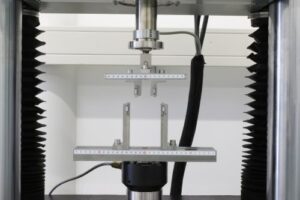
 For the peel test, a universal testing machine with a 100 N load cell and a hydraulic clamp is used. The test setup also includes a flat base plate on which the test specimen is placed. For preparation, lines are drawn on the shell of each specimen at 1-inch intervals using a permanent marker, and the implant is cut along these lines with a razor blade.
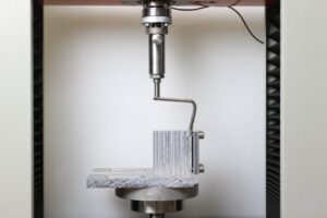
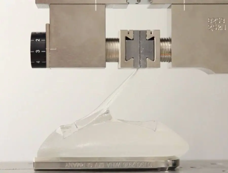
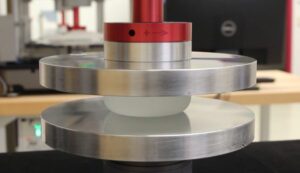
 For the gel compression fracture test, a universal testing machine equipped with a 100 N load cell and a compression platen with a diameter of 15 mm is used. The test setup includes a flat plate on which the sample is placed. Compression is applied at a speed of 1 inch per minute. The compressive force exerted on the gel is measured until a drop in force indicates the point of gel fracture. A higher compressive force indicates greater resistance to gel fracture.
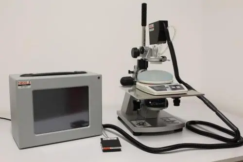
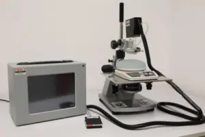 The testing of gel material properties is conducted using our proprietary BTC-2000 device. The suction unit, which holds the laser unit, is mounted on a microscope stand with a micrometer drive. A scale is positioned on the microscope stand. The basic principle of gel elasticity testing involves applying a vacuum to a portion of the implant gel inside the cylindrical chamber of the suction unit and measuring the gel deformation with a laser. A 1 cm circular area of the implant shell is removed from the apex of the implant, and the gel is dusted with laser toner to enhance laser tracking of the surface.
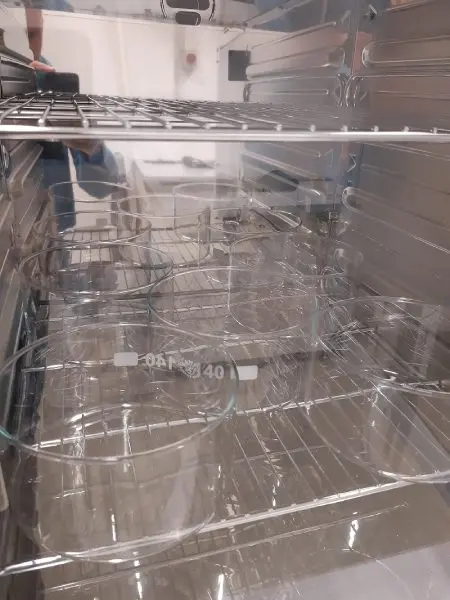
 ASTM F703 describes a test for silicone implants to assess gel bleeding. This test checks the implant for the migration of silicone gel through the elastomer shell. The implants are placed on platinum-cured silicone discs (70 durometer) with a diameter of 50 mm and stored for 8 weeks at 43.3°C. The weight of the silicone discs is measured weekly to determine any change in weight. Control discs, stored under the same conditions without implants, are used to account for variations due to environmental factors. ASTM requires a minimum of three samples of each implant type and three additional control discs.
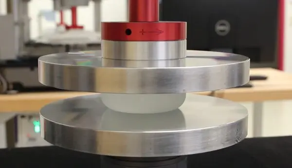
 ISO 14607 (2007 edition) describes in section E.3 the testing of the static rupture strength of breast implants. In addition to fatigue tests according to the 2018 edition and FDA guidelines, we also offer the static rupture test according to the 2007 edition.