")


Procedures for the mechanical testing of trauma and osteosynthesis implants
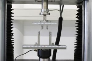 We offer a testing procedure in accordance with ASTM F382 for comparing bone plates with respect to their mechanical properties. Specifically, the following two tests can be performed
- Static four-point bending test The bone plate is positioned in the test fixture and loaded until a significant drop in force occurs (fracture or material yielding). During the test, a force–displacement diagram is recorded and evaluated with respect to bending stiffness and bending strength.
- Dynamic four-point bending test The bone plate is clamped in the test fixture and subjected to loading over a defined number of cycles. The applied load should correspond to 75, 50, or 25% of the bending strength and be applied at a frequency of 1–10 Hz. Subsequently, an M–N diagram (maximum bending moment versus number of cycles) is generated and the fatigue strength is determined.
In addition to the mechanical characterization of bone plates, we are also pleased to advise you on correct labeling, packaging, and the content of the manufacturer information to be provided with the product.
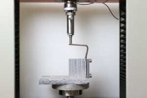 We offer characterization of angled plates in accordance with ASTM F384. Specifically, we can perform static and dynamic bending tests:
- Static bending test The angled plate is fixed to a rigidly clamped test block via the side plate, while the angled portion of the implant remains free. A constant displacement acting parallel to the side plate is applied to the angled portion of the implant (rate: 10 mm/min). Bending stiffness and bending strength are determined from the force–displacement curve.
- Dynamic bending test The angled plate is aligned in the same manner as in the static bending test and loaded over a defined number of cycles. The applied load should correspond to 75, 50, or 25% of the bending strength and be applied at a frequency of 1–10 Hz. Subsequently, an M–N diagram (maximum bending moment versus number of cycles) is generated and the fatigue strength is determined.
In addition to the mechanical characterization of angled plates, we are also pleased to advise you on correct labeling, packaging, and the content of the manufacturer information to be provided with the product.
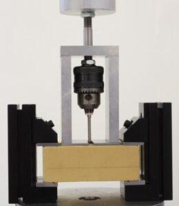 We offer various test methods for the mechanical characterization and classification of bone screws in accordance with ASTM F543. Together with you, we select the appropriate test procedures from the following range to suit your specific screw design:
- Test method for determining torsional properties The bone screw is clamped in a fixture and loaded at a constant rotational speed (1–5 rpm) while a torque–rotation angle curve is recorded. This curve is then evaluated with respect to yield point, maximum torsional moment, and fracture angle, enabling a qualitative comparison of different screws.
- Test method for determining insertion and removal torque The screw is inserted into a standardized test block under a constant axial load and at a constant rotational speed (1–5 rpm), and subsequently removed, in order to determine material-independent comparative values for insertion and removal torque.
- Test method for determining axial pull-out strength The screw is inserted into a standardized test block at a constant rotational speed (3 rpm) up to a defined insertion depth and subsequently pulled out axially at a constant speed (5 mm/min) until the screw loosens or fails.
- Test method for determining the cutting performance of self-tapping bone screws To determine the axial force at which the self-tapping action of the screw begins, the screw is inserted into a pre-drilled test block at increasing axial force (1–3 N/s) and a rotational speed of 30 rpm.
- Classification of metallic bone screws Based on various geometric characteristics, screws are classified into categories HA, HB, HC, and HD.
- Classification of the connection between screw head and bit Based on various geometric characteristics, the connections between screw head and bit (drive connection) are specified.
In addition to the mechanical characterization and classification of bone screws, we are also pleased to advise you on correct labeling, packaging, and the content of the manufacturer information to be provided with the product.
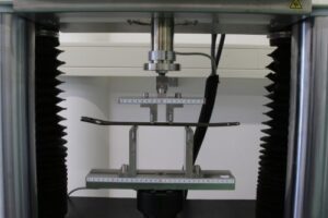 We offer characterization of the design and mechanical performance of intramedullary nails in accordance with ASTM F1264.
- Static four-point bending test An intramedullary nail is clamped in the test fixture and loaded until a significant drop in force occurs (fracture or material yielding). During the test, a force–displacement curve is recorded and evaluated with respect to bending stiffness and bending strength.
- Dynamic four-point bending test An intramedullary nail is clamped in the test fixture and loaded over a defined number of cycles. The applied load should correspond to 75, 50, or 25% of the bending strength and be applied at a frequency of 1–10 Hz. Subsequently, an M–N diagram (maximum bending moment versus number of cycles) is generated and the fatigue strength is determined.
- Static torsion test An intramedullary nail is clamped in the testing machine and a constant axial force (5–10 N) is applied. Subsequently, torsion of 5° is applied at a constant rate of 5°/min. A torque–rotation angle curve is recorded, whose linear slope corresponds to torsional stiffness.
- Dynamic four- or three-point bending test of locking screws The dynamic bending test of the locking screw is performed in accordance with the test procedure used for intramedullary nails.
In addition to the mechanical characterization of intramedullary nails, we are also pleased to advise you on correct labeling, packaging, and the content of the manufacturer information to be provided with the product.
")