")


How Preclinical Testing of Breast Implants Works at INNOPROOF?
Preclinical testing of breast implants is described with international validity in ISO 14607:2024. Fatigue tests (Annexes C.1 and C.3) and impact tests (Annex C.2) are required on the final, sterilized product. With regard to the shell, tensile tests on standardized specimens with measurement of tensile set are required. In addition, the bond between the shell and the seal must be tested in a tensile test (Annex B). For the silicone filling itself, cohesion tests are described in Annex E.
Furthermore, ISO 14607 specifies a measurement of surface topography in Annex G. From this, surface roughness and additional surface parameters are determined, and the classification into smooth, micro-textured, or macro-textured is derived. For inflatable implants, the reliability of the valve or injection site is tested in accordance with Annex D.
For FDA approval, an additional fatigue test must be performed in accordance with FDA Guidance Docket No. 2004D-0124. The aim of this test is the development of a Wöhler (S–N) curve and the determination of the fatigue life of the implant over 6.5 million load cycles. Further tests on breast implants are described in ASTM F703. The mechanical testing of the shell corresponds to Annex B of ISO 14607. The testing of inflatable implants corresponds to Annex D. The cohesion test corresponds to Annex E.
A test method described in ASTM F703 but not in ISO 14607 is the gel bleeding test. Here, the finished, sterilized product is stored for 8 weeks at elevated temperature, and any silicone leakage through the shell is measured. All of the above-mentioned tests are offered by INNOPROOF GmbH for your products. Further information on the individual tests is provided in the sections below.
Our service portfolio has also been expanded to include tests that are not specified by standards but are described in the literature. This includes, for example, testing the elasticity of the gel filling.
The methods accredited within our scope are marked with * below. Within the framework of the MRA-ILAC agreements, our tests are internationally valid.
Procedures for the mechanical testing of breast implants
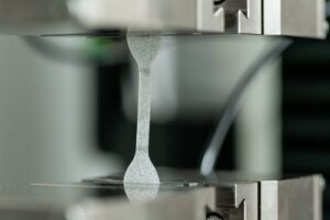 As part of our testing services for breast implants, we offer, among other things, tests to assess the integrity of the shell in accordance with ISO 14607:2024, Annex B. These include tests of the shell’s elongation, measurement of tensile set after sustained elongation, and testing of seam strength.
For the shell tests mentioned above, specimens are first prepared using a standardized die. INNOPROOF has a corresponding cutting die in accordance with ISO 37:2017, Type 2, enabling us to obtain specimens directly from the breast implants. All tests are performed under tensile loading using our Zwick universal testing machine. We would be pleased to provide you with a quotation for these testing services.
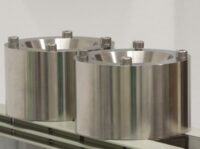
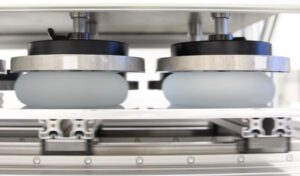 ISO 14607:2024 describes in Annex C.1 the fatigue testing of breast implants under shear stress. The implant is placed between two horizontally arranged plates, and a static load of 50 N per implant is applied. Using an eccentric drive, one of the plates is moved back and forth, applying shear stress to the implant. The test is conducted over 6.5 million cycles at a frequency of 3.33 Hz. Afterwards, an optical rupture inspection is performed.
We offer this test as a service and can test six breast implants of various sizes simultaneously on our test rig. We would be happy to provide you with a quote.
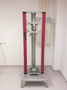 For the impact test according to ISO 14607:2024 Annex C.2, INNOPROOF has developed and built a custom drop rig that ensures a standard-compliant test. Depending on the mass and projection height of the breast implant, the required drop height is calculated. A weight of 4.4 kg is held by an electromagnet, and the drop height is set using a measuring device. The test specimen is placed centrally on the test table. When the electromagnet is switched off, the weight is released, initiating the impact.
After the impact test, the breast implant undergoes a visual inspection. To pass the test, no damage to the shell may be visible.
For the impact test according to ISO 14607:2024 Annex C.2, INNOPROOF has developed and built a custom drop rig that ensures a standard-compliant test. Depending on the mass and projection height of the breast implant, the required drop height is calculated. A weight of 4.4 kg is held by an electromagnet, and the drop height is set using a measuring device. The test specimen is placed centrally on the test table. When the electromagnet is switched off, the weight is released, initiating the impact.
After the impact test, the breast implant undergoes a visual inspection. To pass the test, no damage to the shell may be visible.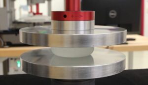 ISO 14607:2024 Annex C.3 and the document Docket No. 2004D-0124 from the U.S. Food and Drug Administration (FDA) describe fatigue tests on breast implants aimed at developing a Wöhler (S–N) curve. Unlike the fatigue tests under shear stress according to ISO 14607, the implants in the FDA guideline Docket No. 2004D-0124 are subjected to cyclic compressive loading. Sinusoidal load cycles with defined upper and lower loads are applied up to a run-out level of 6.5 million cycles. We offer this test together with static rupture tests according to ISO 14607:2007.
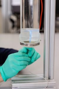 Annex D of ISO 14607:2024 describes the testing of the injection site of fillable tissue expanders (breast implants). The injection site is repeatedly pierced at the same spot with a needle while a water column exerts pressure on the passage.
The injection site must not show any leakage as a result of the punctures and after a waiting period of 30 seconds. We offer injection site testing with specimen preparation as part of our breast implant testing services.
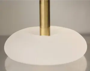
 We offer cohesion testing of silicone gel according to ISO 14607:2024 Annex E. In this test, only the filling is examined, not the shell. The silicone filling material is poured into a funnel with standardized dimensions and surface roughness. The gel is allowed to flow freely through the funnel’s lower opening for a duration of (30.0 ± 0.1) minutes.
During the test, it is observed whether the flowing filling material separates from the remaining volume in the funnel. If the material remains cohesive as a whole, the length of the portion hanging below the funnel is measured. We would be happy to provide you with a quotation for this test.
 The testing of surface characteristics of breast implants according to ISO 14607:2024 is used to determine the surface roughness (Sa) as well as the surface complexity (Scx). Together with the type of surface texturing, this allows classification of the implant surface.
For roughness measurements, we use a confocal laser scanning microscope. The surface topography is scanned at magnifications of 10x or 20x. In addition to the arithmetic surface roughness (Sa), we also determine further parameters upon customer request, such as root mean square height (Sq), skewness (Ssk), kurtosis (Sku), maximum peak height (Sp), maximum pit height (Sv), maximum height (Sz), or density of peaks (Spd). The surface complexity (Scx) is determined using our digital microscope VHX-7000.
We use the proven punching technique according to ISO 37 to create as flat a cross-section as possible on the implant shell for the measurements. During evaluation, the complexity of the surface texture is determined in two-dimensional space.
- ISO 14607 (2007 edition) describes in section E.3 the testing of the static rupture strength of breast implants. In addition to fatigue tests according to the 2018 edition and FDA guidelines, we also offer the static rupture test according to the 2007 edition.
Please feel free to contact us if you are interested in other methods for the mechanical testing of breast implants.
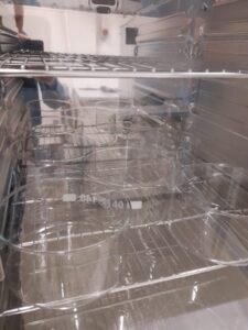 ASTM F703 describes a test for silicone implants to assess gel bleeding. This test checks the implant for the migration of silicone gel through the elastomer shell. The implants are placed on platinum-cured silicone discs (70 durometer) with a diameter of 50 mm and stored for 8 weeks at 43.3°C. The weight of the silicone discs is measured weekly to determine any change in weight. Control discs, stored under the same conditions without implants, are used to account for variations due to environmental factors. ASTM requires a minimum of three samples of each implant type and three additional control discs.
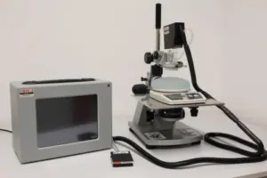 The testing of gel material properties is conducted using our proprietary BTC-2000 device. The suction unit, which holds the laser unit, is mounted on a microscope stand with a micrometer drive. A scale is positioned on the microscope stand. The basic principle of gel elasticity testing involves applying a vacuum to a portion of the implant gel inside the cylindrical chamber of the suction unit and measuring the gel deformation with a laser. A 1 cm circular area of the implant shell is removed from the apex of the implant, and the gel is dusted with laser toner to enhance laser tracking of the surface.
The implant sample is placed on the scale, which is then tared. The cylindrical BTC test chamber is lowered onto the gel surface using the micrometer drive until a force of 5 g is registered on the scale. A vacuum is applied in the suction unit at a rate of 1 millimeter of mercury (mm Hg) per second until reaching 15 mm Hg. Deformation (mm) and pressure (mm Hg) values are recorded.
The resulting value, called “elastic deformation,” is defined as the deformation measured at maximum vacuum, representing the elastic response to the applied pressure. Higher values indicate “softness,” while lower deformations indicate “firmness.”
Reference: Kinney BM, Jeffers LLC, Ratliff GE, Carlisle DA. Silicone gel breast implants: science and testing. Plast Reconstr Surg. 2014 Jul;134(1 Suppl):47S-56S.
 For the gel compression fracture test, a universal testing machine equipped with a 100 N load cell and a compression platen with a diameter of 15 mm is used. The test setup includes a flat plate on which the sample is placed. Compression is applied at a speed of 1 inch per minute. The compressive force exerted on the gel is measured until a drop in force indicates the point of gel fracture. A higher compressive force indicates greater resistance to gel fracture.
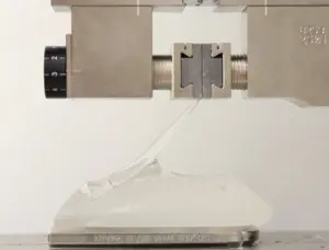 For the peel test, a universal testing machine with a 100 N load cell and a hydraulic clamp is used. The test setup also includes a flat base plate on which the test specimen is placed. For preparation, lines are drawn on the shell of each specimen at 1-inch intervals using a permanent marker, and the implant is cut along these lines with a razor blade.
The test specimen is placed on the base plate in the testing machine, and one inch of the elastomeric shell is peeled away from the gel. The now free end of the shell is clamped in the machine’s hydraulic clamp and adjusted so that the force is evenly distributed across the cross-section of the specimen. The force is zeroed, and the elastomeric shell is pulled at a speed of 20 inches per minute.
The maximum force required to separate the shell from the gel is measured. The number of measurements per specimen depends on the surface area of the sample but should be at least two. The recorded maximum force values are then averaged.
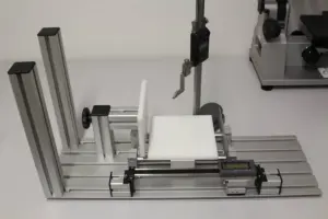 For the morphological analysis, a test setup based on Jewell et al. 2018 was constructed. The setup consists of a sliding table that holds the breast implant sample. The sliding table is moved so that the specimen touches the stationary plate stop. The movable plate stop is connected to a horizontal caliper to measure the width of the implant. A digital height gauge is mounted next to the setup to measure projection and pole depth. The setup also allows assisted vertical alignment of the specimen.
Measured parameters include width, height, lower pole depth, and upper pole depth for anatomically shaped implants, and height, overhang, and upper pole depth for round implants. Each parameter is measured three times per device, with the implant removed and repositioned between measurements. The maximum projection for anatomically shaped implants is defined as the depth of the lower pole in a horizontal position, and the maximum projection for round implants is defined as the apex in the center of the device. The upper pole depth is the thickness of the upper pole, defined as 17% of the average horizontal height measured from the top of an anatomically shaped implant, or 25% of the average horizontal height measured from the top of a round implant.
For the morphological analysis, a test setup based on Jewell et al. 2018 was constructed. The setup consists of a sliding table that holds the breast implant sample. The sliding table is moved so that the specimen touches the stationary plate stop. The movable plate stop is connected to a horizontal caliper to measure the width of the implant. A digital height gauge is mounted next to the setup to measure projection and pole depth. The setup also allows assisted vertical alignment of the specimen.
Measured parameters include width, height, lower pole depth, and upper pole depth for anatomically shaped implants, and height, overhang, and upper pole depth for round implants. Each parameter is measured three times per device, with the implant removed and repositioned between measurements. The maximum projection for anatomically shaped implants is defined as the depth of the lower pole in a horizontal position, and the maximum projection for round implants is defined as the apex in the center of the device. The upper pole depth is the thickness of the upper pole, defined as 17% of the average horizontal height measured from the top of an anatomically shaped implant, or 25% of the average horizontal height measured from the top of a round implant.
Reference: Jewell ML, Bengtson BP, Smither K, Nuti G, Perry T. Physical Properties of Silicone Gel Breast Implants. Aesthet Surg J. 2019 Feb 15;39(3):264-275
")