")


Procedures for the mechanical testing of hip replacement
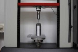
 The tests according to ISO 7206-4 and ISO 7206-6 focus on the stem and neck regions of the femoral component of hip replacements. Under specified cyclic loads and numbers of cycles, the fatigue strength of the hip stem is evaluated. The fixation method and applied loads vary depending on the design and length of the stem, which is classified as short stem, standard stem, or revision stem.
Additional requirements arise depending on whether the design is anatomical or straight. If the product features taper connections in the stem or neck area, the tests are performed in a saline bath at 37°C.
Beyond the prescribed standard conditions, we offer, in consultation with our customers, testing with higher loads, increased cycle numbers, and load increments.
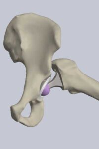 The procedure specified in ISO 21535 measures the range of motion (ROM) of hip replacements. This can be performed either on the actual component or within a CAD environment. The ranges of motion up to impingement are measured in the directions of flexion/extension, adduction/abduction, and internal/external rotation.
The standard defines minimum rotation angles that the product must be able to achieve before impingement occurs.
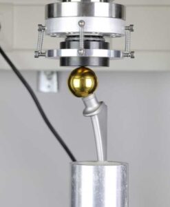
 This test evaluates the fixation of inserts in the acetabular shell to compare the effectiveness of different insert fixation mechanisms. It includes three different tests. The shell is fixed in all tests using a suitable fixture to prevent movement of the shell while allowing the insert to be released. Before each test, the insert is fixed in the shell with a force of 2000 N (ASTM F2345).
Axial push-out test A displacement is applied to the insert along the polar axis through a hole in the pole of the acetabular shell until the insert detaches from the shell. The resulting force is measured. Offset pull-out test or lever-out test For this test, a slot or hole is first created inside the insert at approximately 80% of its depth. Then, an axial displacement parallel to the polar axis is applied to the insert via a rod (offset pull-out test). Alternatively, the insert can be levered out using a lever arm that engages the slot or hole (lever-out test). Torsion test For this test, grooves parallel to the polar axis are introduced into the insert, into which springs on a prepared ball head engage. Alternatively, a ball head can be glued into the insert. Then, torsion is applied around the polar axis via the ball head until the insert is released.
")