Mechanical testing of sports shoes

Which mechanical tests on sports shoes does our laboratory offer?

In the sole fatigue test, the running behavior of a jogger performing hundreds of thousands of steps is simulated. The sole is repeatedly loaded and unloaded to realistically reproduce long-term use. Afterwards, the ability of the sole to recover and return to its original shape is evaluated. In addition, changes in cushioning, stiffness, and other mechanical properties caused by long-term cyclic loading are analyzed.
In this test, various sole materials such as EVA, TPU, or PEBA are subjected to defined impact loads. The objective is to objectively measure the cushioning behavior and energy absorption of the individual foam materials. After the loading tests, the materials are compared with respect to their mechanical properties. This makes it possible to determine which foam provides the best performance under identical conditions.
Impact and drop tests simulate hard impact loads such as those occurring during running or jumping. In particular, the heel area is subjected to defined impact forces. Measurements determine how effectively the shoe absorbs and distributes impact energy. In addition, the tests evaluate whether material damage or permanent deformations occur.
In bending and torsion tests, the shoe is repeatedly bent and twisted to replicate natural foot movements. These tests show how flexible or stiff the shoe is in both longitudinal and transverse directions. At the same time, it is evaluated whether materials or bonded joints begin to separate over time. The results provide important information about the stability and wearing comfort of the shoe.
Shear testing evaluates how well materials and material joints withstand lateral forces. Controlled shear forces are applied to the sole or to bonded interfaces between different layers. The objective is to assess adhesion strength and structural stability. This makes it possible to determine whether materials shift or separate under lateral loading.

Which types of sports shoes are tested?

  • Running shoes (road, trail, competition)
  • Football boots (natural grass, artificial turf, indoor)
  • Basketball shoes
  • Handball shoes
  • Volleyball shoes
  • Tennis shoes
  • Fitness and training shoes
  • Hiking shoes
  • Climbing shoes
Prüflabor für Sportschuhe

Contact us

In 5 steps to a test report for sports shoes

Why should you have your sports shoes tested by Innoproof?

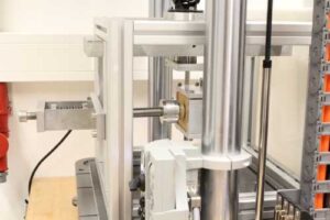
State-of-the-art testing technology

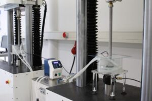
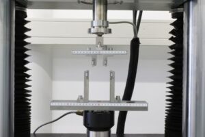
Our testing laboratory is equipped with state-of-the-art machines, such as the Instron Electropuls E3000. This technology enables precise, reproducible, and dynamic testing at the highest level. This ensures that your products are tested under realistic and precisely controlled conditions.

Owner-managed company with direct communication

As an owner-managed medium-sized company, we offer short decision-making paths and direct communication. Our customers benefit from quick availability and dedicated contacts throughout the entire project. This ensures efficiency, trust, and a collaborative partnership.

Meaningful test reports with added value

Our test reports are not only technically accurate but also clearly structured and easy to understand. High-quality images, clear graphics, and detailed explanations make results transparent and easy to compare. This provides you with a solid basis for decisions in development, quality assurance, and communication.

Sustainable testing without hydraulic oil systems

We deliberately avoid environmentally harmful hydraulic oil systems and rely exclusively on electrodynamic testing systems. This approach is more energy-efficient, cleaner, and requires less maintenance. In this way, we combine state-of-the-art testing technology with responsible use of resources.

2. February 2026|

Failure analysis of implants and medical devices

Typical investigations performed as part of failure analysis of implants and medical devices include the following:

  • Digital microscopy: Analysis for visual abnormalities, contamination, corrosion, abrasion, wear mechanisms, and notch effects (non-destructive)
  • Determination of wear volume: Tactile measurement of wear volume in mm³ (non-destructive)
  • SEM and EDX examination of fracture surfaces, analysis of fracture type and crack origin, as well as material composition (partially destructive)
  • Metallographic cross-section analysis of implant material (destructive), including microstructure evaluation and examination for inclusions and voids
2. February 2026|

Mechanical and chemical testing of surgical instruments

Methods for the mechanical and chemical testing of surgical instruments

  • Mechanische und chemische Prüfung von chirurgischen InstrumentenASTM F1089 describes physicochemical investigations of surgical instruments with a focus on corrosion.
  • We test the mechanical requirements for root canal instruments in accordance with DIN EN ISO 3630-1:2008 and are accredited to perform testing of torsional strength and angular deflection (Section 7.4) as well as bending resistance (Section 7.5).
  • DIN EN ISO 11953 describes a test concerning torque wrenches used for the placement of dental implants. The objective is to verify the repeatability of the torque indication or the triggering accuracy of the torque wrench. The operating principle of torque wrenches may be based on different mechanisms, such as a bending beam with scale indication or a ratchet mechanism that signals the target torque by a clicking sound.

    In clinical practice, the key question is how precisely torque values are maintained after repeated use. Using our torque testing system, combined with intermediate endurance testing and reprocessing procedures, we simulate long-term use under accelerated conditions.

2. February 2026|

Mechanical testing of implant coatings

Methods for the mechanical testing of implant coatings

  • ASTM F 1044 Scherfestigkeit* 
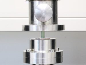
The static testing of coating shear strength is described in ASTM F1044. The joining of the specimens and their alignment in the testing machine correspond to those used in dynamic tests. The opposing, bonded layers are vertically aligned with their contact surface in the loading axis of the testing machine in order to ensure pure shear loading without bending. The specimen holders are mounted on double Cardan joints to decouple constraint forces.
  • ASTM F 1147 Zugfestigkeit* ASTM F1147 specifies a static test setup for determining the tensile or adhesive strength of coatings. The coating is applied to the end face of a cylinder, which is bonded to a second cylinder according to a defined protocol prior to testing. The opposing bonded layers are axially aligned with their contact surface in the loading axis of the testing machine in order to ensure pure tensile loading. The specimens are mounted on double Cardan joints to decouple constraint forces.
  • ASTM F 1044 Scherfestigkeit* For testing the shear strength of coatings, ISO 13179-1:2014 specifies dynamic tests that reference the corresponding method in ASTM F1160-14. The coating is applied to the end faces of two cylinders, which are bonded together prior to testing.

    The opposing bonded layers are vertically aligned with their contact surface in the loading axis of the testing machine to ensure pure shear loading without bending. The specimen holders are mounted on double Cardan joints to decouple constraint forces.

    The ISO standard requires 10 million load cycles for a successful test.

  • ASTM F 1978 Abriebbeständigkeit von Beschichtungen* We offer measurement of the abrasion resistance of metallic thermal spray coatings using a Taber Abraser in accordance with ASTM F1978-18. The coating under investigation is subjected to controlled pressure and abrasion conditions on rotating discs. The specimen, mounted on a rotating platform, turns about a vertical axis against the sliding rotation of two abrasive wheels. One wheel abrades the specimen outward toward the periphery, while the other abrades inward toward the center.

    The resulting abrasion marks form a pattern of crossed arcs over an area of approximately 30 cm². After a defined number (2, 5, 10, or 100) of cumulative rotation cycles, the specimens are cleaned in an ultrasonic bath. After each cleaning step, the specimens are dried and weighed. The mass loss serves as a measure of the abrasive wear of the specimen. INNOPROOF is accredited to perform this test.

2. February 2026|

Mechanical testing of medical gloves

Methods for the mechanical testing of medical gloves

  • DIN EN 455-4 Haltbarkeit von Handschuhen* 
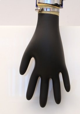
According to DIN EN 455-1, a water leak test can be performed to verify the watertightness of disposable gloves. Using a vertical tube, 1000 ml of water at a temperature between 15 °C and 35 °C is filled into the glove to be tested. The glove is immediately visually inspected for leaks. The glove is considered non-watertight as soon as water leakage occurs. After 2 to 3 minutes, the glove is visually inspected again.
  • DIN EN 455-2 Physikalische Eigenschaften von Handschuhen*
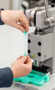
According to DIN EN 455-2, the dimensions and the tensile strength of a medical disposable glove are determined. At least 13 samples per glove batch are used. For dimensional verification, the glove length and width are measured using a ruler and compared with the size table specified in the standard.

    Depending on the intended use of the gloves, different dimensional requirements apply. For determination of tensile strength, dumbbell-shaped specimens are punched from the palm area of the gloves. The single wall thickness of the glove and the thickness of the dumbbell specimen are measured. The statically determined tensile force is multiplied by the ratio of single wall thickness to specimen thickness. The resulting tensile force value is then compared with the values specified in the standard.

  • The gloves are stored in consumer packaging for the intended shelf life at a temperature specified by the manufacturer. Afterwards, the gloves are tested for watertightness according to EN 455-1 and for tensile strength according to EN 455-2. The integrity of the packaging and the suitability of the gloves for their intended use are also verified. The shelf life corresponds to the time at which all specified tests are still successfully passed.
2. February 2026|

Mechanical testing of packaging for medical devices

Video of the ASTM F2096 Bubble Emission Test

Methods for the mechanical testing of medical packaging

  • ASTM D642 Kompressionsprüfung
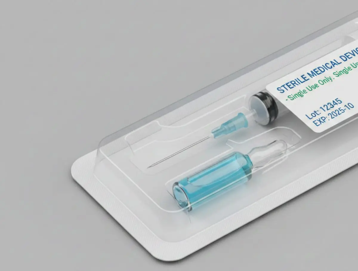
Packaging is tested under compression according to ASTM D642 in order to simulate transportation or storage conditions. The packaging sample is placed between two horizontal plates and subjected to static loading. The test is terminated when a specified deformation is reached or when a drop in reaction force occurs. The maximum applied test force and the corresponding deformation of the packaging are recorded.
  • ASTM F88 Siegelnahtprüfung
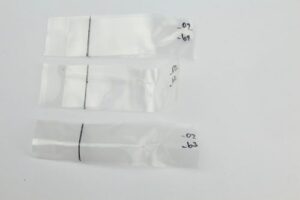
The seal strength of the packaging seam is tested in a tensile test. The packaging is cut into samples of defined size. Both ends of the seal are clamped, with one of three clamping configurations selected depending on the type of seal. The specimen is statically loaded at 200 to 300 mm/min until seal failure occurs. Only results obtained using the same clamping configuration may be compared.
  • The seal is visually inspected in the seam area for sealing defects, uniformity, and completeness.
  • The dimensions of the packaging are determined using a ruler.
  • ASTM F1929 Dichtheitsprüfung mittels Dye Penetration Test
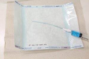
To evaluate the seal seam, dye is applied to one side of the seal. It is then visually examined whether the dye penetrates through the seal. Each side of the sample seal is observed for 5 seconds. The package must not contain liquids or condensation, as this could distort the test results. The dye used must provide strong contrast with the opaque packaging material. One of three methods is selected for seal testing.

    Method A: Injection method
    The dye solution is injected into the package. The seal is observed to detect possible seal defects indicated by dye leaking from the inside to the outside.

    Method B: Edge immersion method
    An outer edge of the seal is immersed in the dye solution. If dye penetrates from the outside to the inside, leakage points are present in the seal.

    Method C: Pipette method
    For this method, one outer edge of the package must remain unsealed. Using a pipette, drops of dye solution are applied to the inner side of the intact seal seam. The seal is then inspected for dye penetration.

  • ASTM F2096 Bubble Emission Test* 
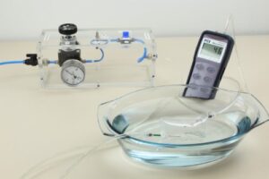
In the bubble emission test according to ASTM F2096, the integrity of packaging or sterile barrier systems is evaluated by applying internal pressure. For this purpose, the packaging film is punctured on one side using a needle, internal air pressure is applied, and the package is submerged in water. In our setup, a second needle and a digital manometer are used to directly measure the internal pressure.

    To validate the procedure and to set the required internal pressure, a hole is intentionally introduced into the packaging using a 250 µm needle. The internal pressure is then adjusted until a continuous stream of air bubbles is produced.

    We are pleased to perform leak testing of your packaging using the bubble emission test.

2. February 2026|

Mechanical testing of bone cements

Procedures of the mechanical testing of bone cements

  • ISO 5833 Knochenzement* 
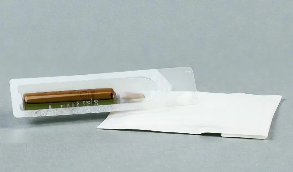
ISO 5833 specifies, among other things, compression and bending tests for bone cement specimens. We offer static compressive strength testing and static bending strength testing as testing services. For bending strength determination, a four-point bending test is performed. If required, bone cement specimens can be manufactured in our laboratory using our own standard-compliant casting molds.

    Testing of dough time is also included within our accredited scope.

    We are also pleased to perform additional tests on bone cement products, such as fatigue tests on cement spacers. Please feel free to contact us!

2. February 2026|

Mechanical testing of spinal implants

Procedures of the mechanical testing of spinal implants

  • ASTM F1717 Korpektomie Modell* 
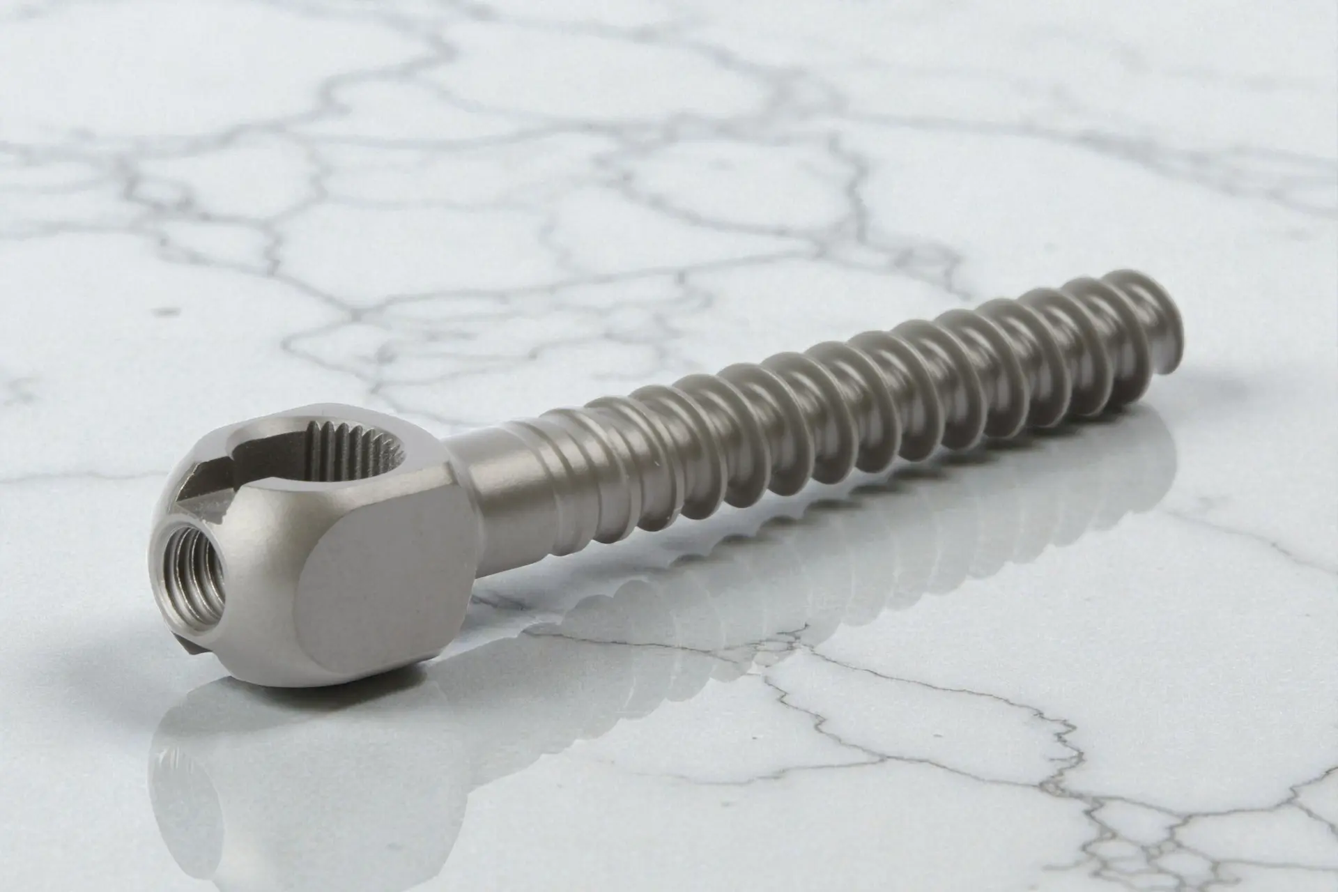
We offer various test methods for the mechanical characterization of spinal implants in a vertebrectomy model in accordance with ASTM F1717. The vertebrectomy model simulates the bridging of a vertebral body without anterior support. The spinal implants are rigidly connected to two UHMWPE blocks with well-defined material properties, while a defined gap between the blocks simulates the absence of a vertebral body. The shape and properties of the test blocks are adapted to different regions of the spine (e.g., lumbar or cervical). Together with you, we select the appropriate test procedures for your individual spinal implants from the following options:

    Static test methods

    1. Bending test under compression: The construct consisting of test blocks and spinal implant is clamped in the test fixture and a compressive load (max. 25 mm/min) is applied. The force–displacement curve is recorded and evaluated with respect to mechanical properties (including stiffness and strength) under compression.
    2. Bending test under tension: The construct consisting of test blocks and spinal implant is clamped in the test fixture and a tensile load (max. 25 mm/min) is applied. The force–displacement curve is recorded and evaluated with respect to mechanical properties (including stiffness and strength) under tension.
    3. Axial torsion: The construct consisting of test blocks and spinal implant is clamped in the test fixture and subjected to constant torsion (max. 60°/min). The axial load should be approximately zero. The torque–rotation angle curve is recorded and evaluated with respect to mechanical properties (including stiffness and strength) under torsion.

    Dynamic test methods

    Following the static investigations, tests are performed dynamically using new specimens over 5 million cycles. A constant ratio between maximum and minimum load of R = 10 must be maintained. The maximum load is initially selected freely. If the implants survive 5 million cycles, the load is adjusted and testing repeated. Ultimately, the difference between two load levels at which the implant fails dynamically or survives should be less than 10%. Tests are conducted under laboratory conditions (air and room temperature), but can also be repeated in Ringer’s solution at 37 °C if required, in order to simulate physiological environmental conditions and possible corrosive effects. INNOPROOF GmbH is accredited for dynamic testing.
  • ASTM F2077 Fusionsimplantate* We offer various test methods for the mechanical characterization of spinal fusion implants in accordance with ASTM F2077. Together with you, we select the appropriate test procedures for your individual fusion implants from the following options:

    Static test methods

    1. Compression test: The fusion implant is placed between two steel blocks and clamped in the test fixture. The surfaces of the blocks are adapted to the implant geometry. The construct is loaded with a constant displacement (max. 25 mm/min), and the force–displacement curve is recorded and evaluated with respect to mechanical properties (including stiffness and strength) under compression.
    2. Shear test: This test is performed in the same manner as the compression test, except that the lower block has a base inclined by 27° or 45°. As a result, both compressive and shear loads act on the implant.
    3. Axial torsion: As in the compression and shear tests, the fusion implant is clamped between two blocks. Depending on the intended implantation region of the spine, an axial preload of 100 N (cervical), 300 N (thoracic), or 500 N (lumbar) is applied. While maintaining constant axial load, a rotation is applied at a constant rate (60°/min), and a torque–rotation angle curve is recorded. This curve is evaluated with respect to mechanical properties (including stiffness and strength) under torsion.

    Dynamic test methods

    Following the static investigations, tests are performed dynamically using new specimens over 5 million cycles, with test blocks made of polyacetal. A constant ratio between maximum and minimum load of R = 10 must be maintained for dynamic compression and shear tests, and R = 1 for dynamic torsion tests. The maximum load should correspond to 25%, 50%, or 75% of the respective maximum load. Ultimately, the difference between two load levels at which the implant either fails dynamically or survives should be less than 10%. The test ends when 5 million load cycles are reached or when mechanical failure of the implants occurs. Tests are conducted under laboratory conditions (air and room temperature), but can also be repeated in Ringer’s solution at 37 °C if required to simulate physiological environmental conditions and possible corrosive effects.
2. February 2026|

Mechanical testing of trauma and osteosynthesis implants

Procedures for the mechanical testing of trauma and osteosynthesis implants

  • ASTM F382 Biegeprüfung Knochenplatten*We offer a testing procedure in accordance with ASTM F382 for comparing bone plates with respect to their mechanical properties. Specifically, the following two tests can be performed

    • Static four-point bending test The bone plate is positioned in the test fixture and loaded until a significant drop in force occurs (fracture or material yielding). During the test, a force–displacement diagram is recorded and evaluated with respect to bending stiffness and bending strength.
    • Dynamic four-point bending test The bone plate is clamped in the test fixture and subjected to loading over a defined number of cycles. The applied load should correspond to 75, 50, or 25% of the bending strength and be applied at a frequency of 1–10 Hz. Subsequently, an M–N diagram (maximum bending moment versus number of cycles) is generated and the fatigue strength is determined.

    In addition to the mechanical characterization of bone plates, we are also pleased to advise you on correct labeling, packaging, and the content of the manufacturer information to be provided with the product.

  • ASTM F384 Biegeversuch an Nagelplatten* 
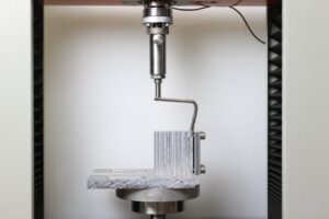
We offer characterization of angled plates in accordance with ASTM F384. Specifically, we can perform static and dynamic bending tests:

    • Static bending test The angled plate is fixed to a rigidly clamped test block via the side plate, while the angled portion of the implant remains free. A constant displacement acting parallel to the side plate is applied to the angled portion of the implant (rate: 10 mm/min). Bending stiffness and bending strength are determined from the force–displacement curve.
    • Dynamic bending test The angled plate is aligned in the same manner as in the static bending test and loaded over a defined number of cycles. The applied load should correspond to 75, 50, or 25% of the bending strength and be applied at a frequency of 1–10 Hz. Subsequently, an M–N diagram (maximum bending moment versus number of cycles) is generated and the fatigue strength is determined.

    In addition to the mechanical characterization of angled plates, we are also pleased to advise you on correct labeling, packaging, and the content of the manufacturer information to be provided with the product.

  • ASTM F543 Kortikale Knochenschrauben* 
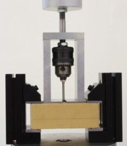
We offer various test methods for the mechanical characterization and classification of bone screws in accordance with ASTM F543. Together with you, we select the appropriate test procedures from the following range to suit your specific screw design:

    • Test method for determining torsional properties The bone screw is clamped in a fixture and loaded at a constant rotational speed (1–5 rpm) while a torque–rotation angle curve is recorded. This curve is then evaluated with respect to yield point, maximum torsional moment, and fracture angle, enabling a qualitative comparison of different screws.
    • Test method for determining insertion and removal torque The screw is inserted into a standardized test block under a constant axial load and at a constant rotational speed (1–5 rpm), and subsequently removed, in order to determine material-independent comparative values for insertion and removal torque.
    • Test method for determining axial pull-out strength The screw is inserted into a standardized test block at a constant rotational speed (3 rpm) up to a defined insertion depth and subsequently pulled out axially at a constant speed (5 mm/min) until the screw loosens or fails.
    • Test method for determining the cutting performance of self-tapping bone screws To determine the axial force at which the self-tapping action of the screw begins, the screw is inserted into a pre-drilled test block at increasing axial force (1–3 N/s) and a rotational speed of 30 rpm.
    • Classification of metallic bone screws Based on various geometric characteristics, screws are classified into categories HA, HB, HC, and HD.
    • Classification of the connection between screw head and bit Based on various geometric characteristics, the connections between screw head and bit (drive connection) are specified.

    In addition to the mechanical characterization and classification of bone screws, we are also pleased to advise you on correct labeling, packaging, and the content of the manufacturer information to be provided with the product.

  • We offer various test methods for the mechanical characterization of bone staples in accordance with ASTM F564. Together with you, we select the appropriate test procedures for your bone staples from the following range:

    • Static bending test A bone staple is clamped in the test fixture and loaded in a four-point bending test at a constant speed of 25.4 mm/min. A force–displacement curve is recorded, and bending stiffness and bending strength are determined.
    • Dynamic bending test Two different dynamic bending tests are offered: a four-point bending test and a combined tensile or compressive and bending load test. In both cases, the bone staples are firmly clamped in the test fixture and cyclically loaded (50% or 75% of the static bending strength). The test ends when the bone staples fracture or when a defined number of cycles has been reached. The test is performed in liquid at 37 °C.
    • Pull-out test (staple/bone) A bone staple is inserted into bone (or an analogous test material) and subsequently removed at a constant speed. A force–displacement curve is recorded, in which a significant drop in force indicates the pull-out force. Upon request, this test can also be performed in liquid to better simulate physiological conditions.
    • Holding strength in soft tissue A bone staple (or multiple staples) is used to create a connection between soft tissue and bone (physiological or analogous materials). Subsequently, a tensile load is applied to the soft tissue at a constant speed, perpendicular to the bone staple, while a force–displacement curve is recorded. The test ends when the bone staple is released or one of the materials fails. Upon request, this test can also be performed in liquid to better simulate physiological conditions.

  • ASTM F1264 Intramedulläre Nägel* 
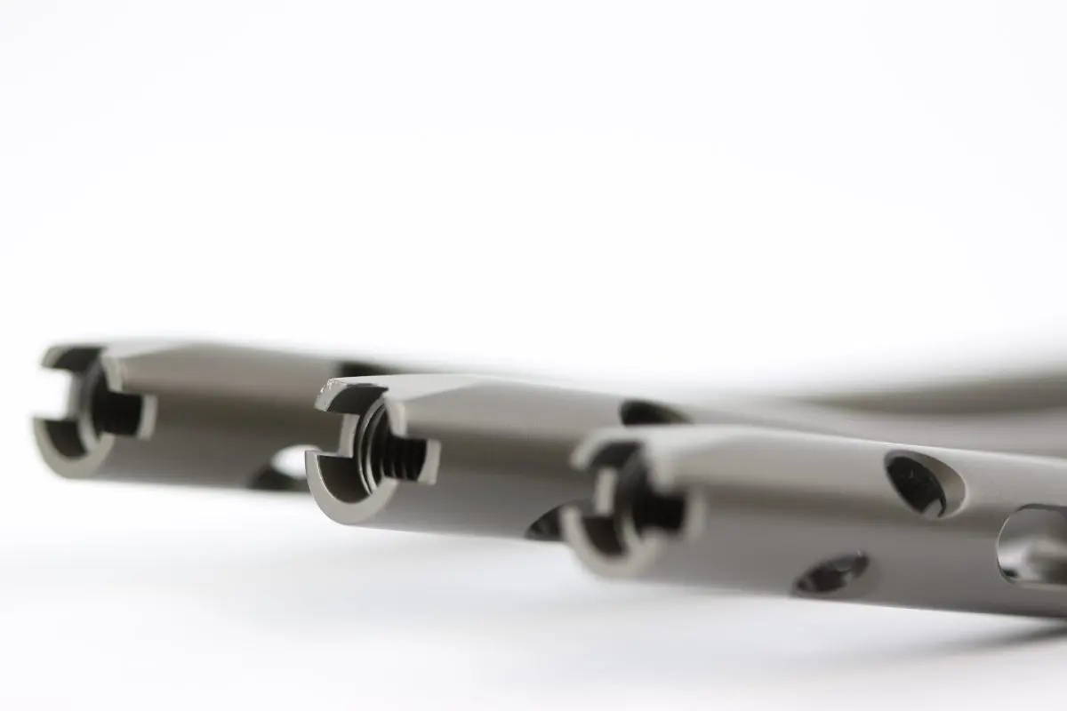
We offer characterization of the design and mechanical performance of intramedullary nails in accordance with ASTM F1264.

    • Static four-point bending test An intramedullary nail is clamped in the test fixture and loaded until a significant drop in force occurs (fracture or material yielding). During the test, a force–displacement curve is recorded and evaluated with respect to bending stiffness and bending strength.
    • Dynamic four-point bending test An intramedullary nail is clamped in the test fixture and loaded over a defined number of cycles. The applied load should correspond to 75, 50, or 25% of the bending strength and be applied at a frequency of 1–10 Hz. Subsequently, an M–N diagram (maximum bending moment versus number of cycles) is generated and the fatigue strength is determined.
    • Static torsion test An intramedullary nail is clamped in the testing machine and a constant axial force (5–10 N) is applied. Subsequently, torsion of 5° is applied at a constant rate of 5°/min. A torque–rotation angle curve is recorded, whose linear slope corresponds to torsional stiffness.
    • Dynamic four- or three-point bending test of locking screws The dynamic bending test of the locking screw is performed in accordance with the test procedure used for intramedullary nails.

    In addition to the mechanical characterization of intramedullary nails, we are also pleased to advise you on correct labeling, packaging, and the content of the manufacturer information to be provided with the product.

  • For fatigue testing of composite sliding nails, INNOPROOF GmbH has established the in-house procedure IP-05-05. The spatial alignment of the sliding nail is based on the testing standard for hip endoprostheses, ISO 7206-4. The load conditions for fatigue testing are defined in consultation with the customer. Typically, tests are performed over 100,000 to 1,000,000 load cycles. If you have questions regarding physiological loads and expected application durations until complete fracture healing, we are happy to provide consultation.
2. February 2026|

Shoulder implant testing

Shoulder implant testing services

  • ASTM F1829 describes a test method to determine the static shear force required to loosen modular glenoid components (insert and backing) of shoulder replacements. The test is suitable for metal joints, polymers, or composites and is used for design validation or comparison with other replacements. Wherever possible, the test should reflect the clinical use of the implant, meaning representative specimens of the finished product are tested and sterilized as required by the manufacturer. For testing, specimens are fixed in the testing machine parallel to the implant axis. A vertical load is first applied from inferior to superior, and the loosening rate is recorded. The test is stopped when one of the following occurs:

    • The insert separates from the backing
    • The applied load reaches its maximum and begins to decrease
    • Gross deformation of the insert occurs without loosening

    After this, a new insert is placed in the test fixture, and the test is repeated under the same conditions but applied from anterior to posterior. The test is stopped again as soon as one of the above cases occurs. The backing is visually inspected for damage after each test. At least five equivalent samples should be tested, and the test can be conducted either in air at room temperature or under defined physiological conditions.
  • ASTM F2028 Glenoid-Lockerungsprüfung* We offer a testing procedure to evaluate the fixation strength of the glenoid component in bone and its resistance to subluxation caused by cyclic movement (e.g., superior-inferior or anterior-posterior) of the humeral head against the edge of the glenoid, according to the ASTM F2028 standard. This test method can be applied to both cemented monolithic and modular glenoid components as well as uncemented reverse glenoid components.

    The glenoid component is fixed in a bone substitute material using bone cement, and the humeral head component is placed into the glenoid component. An axial load is applied through the glenoid component while the humeral head is moved in opposite directions to determine the maximum displacement before dislocation. Then, the humeral head is cyclically moved at a speed of up to 50 mm/min for 100,000 cycles in both directions until 90% of the displacement at dislocation is reached. During the test, axial displacement (rocking) of the glenoid edges is recorded. The test can be conducted dry or in water at 37°C.

2. February 2026|
Go to Top