
Mechanical testing of dental implants
How does the preclinical testing of dental implants at INNOPROOF work?
Below, we present our capabilities for the preclinical testing of dental implants and related instruments. The most important mechanical test is the fatigue test according to ISO 14801:2017. This testing method can also be adapted for bridge constructions. More information can be found below by clicking on the respective sections. In addition to the ISO 14801 test, we offer accredited torsion tests on dental implants according to ISO/TS 13498.
What about surgical instruments? Are you aware of how long torque wrenches last and how precise the torque display remains after numerous uses? To answer these questions, we provide corresponding accredited tests according to ISO 11953.
If you are interested in tests related to endodontics, please also check our “Surgical Instruments” section, where we offer testing of dental files according to ISO 3630-1.
Please contact us or use the call-back function so we can prepare a tailored offer for you.
The methods accredited within our scope are marked with *.
Procedures for the mechanical testing of dental implantology
Nothing Found

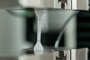 As part of our testing services for breast implants, we offer, among other things, tests to assess the integrity of the shell in accordance with ISO 14607:2024, Annex B. These include tests of the shell’s elongation, measurement of tensile set after sustained elongation, and testing of seam strength.
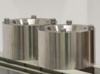
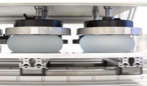 ISO 14607:2024 describes in Annex C.1 the fatigue testing of breast implants under shear stress. The implant is placed between two horizontally arranged plates, and a static load of 50 N per implant is applied. Using an eccentric drive, one of the plates is moved back and forth, applying shear stress to the implant. The test is conducted over 6.5 million cycles at a frequency of 3.33 Hz. Afterwards, an optical rupture inspection is performed.
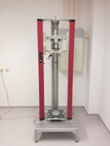 For the impact test according to ISO 14607:2024 Annex C.2, INNOPROOF has developed and built a custom drop rig that ensures a standard-compliant test. Depending on the mass and projection height of the breast implant, the required drop height is calculated. A weight of 4.4 kg is held by an electromagnet, and the drop height is set using a measuring device. The test specimen is placed centrally on the test table. When the electromagnet is switched off, the weight is released, initiating the impact.
After the impact test, the breast implant undergoes a visual inspection. To pass the test, no damage to the shell may be visible.
For the impact test according to ISO 14607:2024 Annex C.2, INNOPROOF has developed and built a custom drop rig that ensures a standard-compliant test. Depending on the mass and projection height of the breast implant, the required drop height is calculated. A weight of 4.4 kg is held by an electromagnet, and the drop height is set using a measuring device. The test specimen is placed centrally on the test table. When the electromagnet is switched off, the weight is released, initiating the impact.
After the impact test, the breast implant undergoes a visual inspection. To pass the test, no damage to the shell may be visible.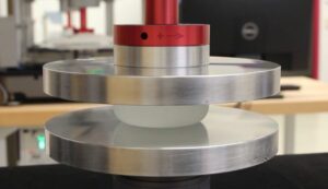 ISO 14607:2024 Annex C.3 and the document Docket No. 2004D-0124 from the U.S. Food and Drug Administration (FDA) describe fatigue tests on breast implants aimed at developing a Wöhler (S–N) curve. Unlike the fatigue tests under shear stress according to ISO 14607, the implants in the FDA guideline Docket No. 2004D-0124 are subjected to cyclic compressive loading. Sinusoidal load cycles with defined upper and lower loads are applied up to a run-out level of 6.5 million cycles. We offer this test together with static rupture tests according to ISO 14607:2007.
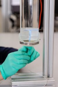 Annex D of ISO 14607:2024 describes the testing of the injection site of fillable tissue expanders (breast implants). The injection site is repeatedly pierced at the same spot with a needle while a water column exerts pressure on the passage.
 We offer cohesion testing of silicone gel according to ISO 14607:2024 Annex E. In this test, only the filling is examined, not the shell. The silicone filling material is poured into a funnel with standardized dimensions and surface roughness. The gel is allowed to flow freely through the funnel’s lower opening for a duration of (30.0 ± 0.1) minutes.
 The testing of surface characteristics of breast implants according to ISO 14607:2024 is used to determine the surface roughness (Sa) as well as the surface complexity (Scx). Together with the type of surface texturing, this allows classification of the implant surface.
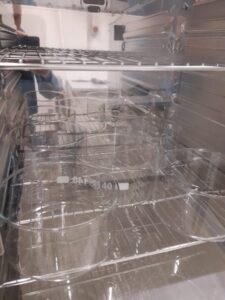 ASTM F703 describes a test for silicone implants to assess gel bleeding. This test checks the implant for the migration of silicone gel through the elastomer shell. The implants are placed on platinum-cured silicone discs (70 durometer) with a diameter of 50 mm and stored for 8 weeks at 43.3°C. The weight of the silicone discs is measured weekly to determine any change in weight. Control discs, stored under the same conditions without implants, are used to account for variations due to environmental factors. ASTM requires a minimum of three samples of each implant type and three additional control discs.
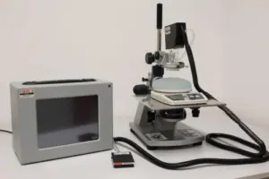 The testing of gel material properties is conducted using our proprietary BTC-2000 device. The suction unit, which holds the laser unit, is mounted on a microscope stand with a micrometer drive. A scale is positioned on the microscope stand. The basic principle of gel elasticity testing involves applying a vacuum to a portion of the implant gel inside the cylindrical chamber of the suction unit and measuring the gel deformation with a laser. A 1 cm circular area of the implant shell is removed from the apex of the implant, and the gel is dusted with laser toner to enhance laser tracking of the surface.
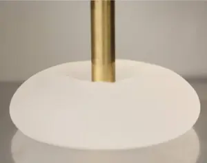 For the gel compression fracture test, a universal testing machine equipped with a 100 N load cell and a compression platen with a diameter of 15 mm is used. The test setup includes a flat plate on which the sample is placed. Compression is applied at a speed of 1 inch per minute. The compressive force exerted on the gel is measured until a drop in force indicates the point of gel fracture. A higher compressive force indicates greater resistance to gel fracture.
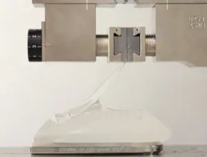 For the peel test, a universal testing machine with a 100 N load cell and a hydraulic clamp is used. The test setup also includes a flat base plate on which the test specimen is placed. For preparation, lines are drawn on the shell of each specimen at 1-inch intervals using a permanent marker, and the implant is cut along these lines with a razor blade.
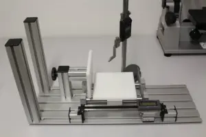 For the morphological analysis, a test setup based on Jewell et al. 2018 was constructed. The setup consists of a sliding table that holds the breast implant sample. The sliding table is moved so that the specimen touches the stationary plate stop. The movable plate stop is connected to a horizontal caliper to measure the width of the implant. A digital height gauge is mounted next to the setup to measure projection and pole depth. The setup also allows assisted vertical alignment of the specimen.
Measured parameters include width, height, lower pole depth, and upper pole depth for anatomically shaped implants, and height, overhang, and upper pole depth for round implants. Each parameter is measured three times per device, with the implant removed and repositioned between measurements. The maximum projection for anatomically shaped implants is defined as the depth of the lower pole in a horizontal position, and the maximum projection for round implants is defined as the apex in the center of the device. The upper pole depth is the thickness of the upper pole, defined as 17% of the average horizontal height measured from the top of an anatomically shaped implant, or 25% of the average horizontal height measured from the top of a round implant.
For the morphological analysis, a test setup based on Jewell et al. 2018 was constructed. The setup consists of a sliding table that holds the breast implant sample. The sliding table is moved so that the specimen touches the stationary plate stop. The movable plate stop is connected to a horizontal caliper to measure the width of the implant. A digital height gauge is mounted next to the setup to measure projection and pole depth. The setup also allows assisted vertical alignment of the specimen.
Measured parameters include width, height, lower pole depth, and upper pole depth for anatomically shaped implants, and height, overhang, and upper pole depth for round implants. Each parameter is measured three times per device, with the implant removed and repositioned between measurements. The maximum projection for anatomically shaped implants is defined as the depth of the lower pole in a horizontal position, and the maximum projection for round implants is defined as the apex in the center of the device. The upper pole depth is the thickness of the upper pole, defined as 17% of the average horizontal height measured from the top of an anatomically shaped implant, or 25% of the average horizontal height measured from the top of a round implant.